


We hit a submerged piece of wood (or something) at the lake right about 20 mph. We didn't even see it. But it was fast enough to bend both the prop and the strut.
So I had to get both repaired. Since I had to pull the driveline anyway I decided to replace the shaft seal system as well. My boat is 11 years old, and I certainly didn't want any unexpected issues later.
For this I chose Glide's Dripless Shaft Seal System (GMSS Kit) because its virtually maintenance free, its dripless, has a great reputation and it even ships in the new Malibus. I also learned more about Glide for our giveaway/drawing on Wake Garage (nope, I didn't win, I had to buy one).... The company's owner was very helpful in answering questions and is passionate about boats. They have a solid reputation and I like supporting good companies. I also learned from other Wake Garage members @Hyperryd and @rhino89523 about their Glide installations, which was helpful.
(In order to pull the driveshaft I had to pull the rudder -- and you might too, depending on your boat.
This is briefly covered in another project here: Rudder Rebuild. )
Here's the Glide GMSS system I installed in this project -- replacing the aging shaft stuffing box.

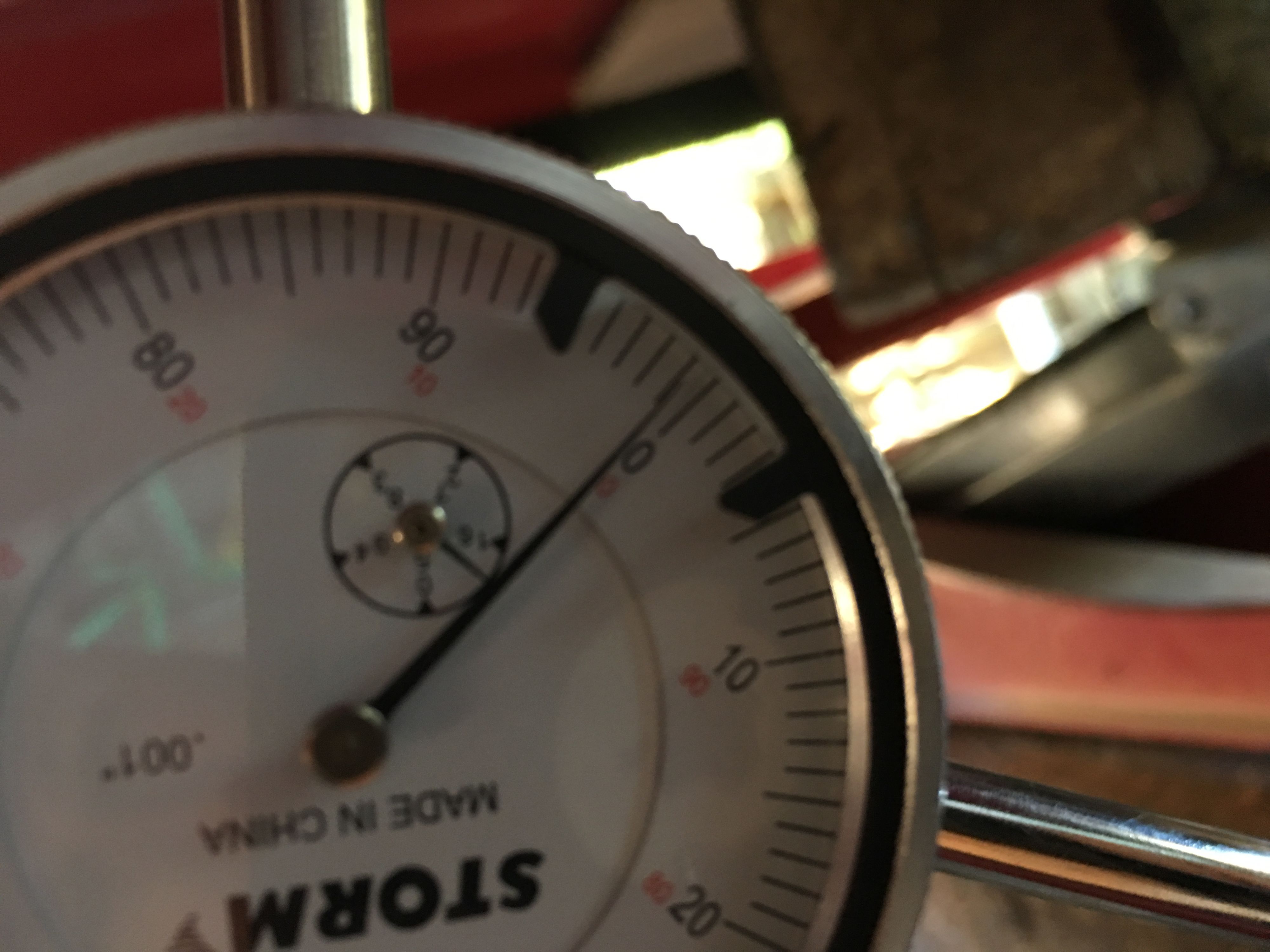
1) CHECK SHAFT Before pulling the driveshaft, I did a hasty check to make sure it was straight after our collision. It spun freely, no jambs, and I used a magnet based dial indicator to measure the drive shaft in multiple areas. I checked it at the top, then by the strut in a few places. I've read that movement needs to be less than three thousands of an inch. Best to take the shaft to a machine shop or propeller service center to have it checeked... but I was comfortable calling mine straight enough.
Terrible picture... sorry.... but if you haven't done this before you can attach the dial indicator magnet to a metal base, such as to the trailer, and then adjust the arms so that the indicator point rests on the drive shaft. Reset the gauge to show "zero". Then spin the drive shaft to see the indicator shows movement in or out. Do this in a few places, top, middle, and at strut, etc.

2) REMOVED COUPLING -- The next step is easy or difficult depending on your boat's access. Direct drives can be much easier. Mine's a V drive and I did not have much room to work, although I know it could be much worse. Removed the 4 bolts attaching the V drive flange to the drive shaft coupler. Mine then had an allen set screw that keeps the nut on the end of driveshaft from spinning, so you need to remove the set screw. If yours does not have a set screw, you likely have a snap ring or something inside.
Removing those bolts was easy, I had good access to work a socket and wrench on one side, then rotated the driveshaft by hand to do the next bolt.


Remove the set screw so the drive shaft nut can be turned.

Access to the drive shaft nut can be difficult. In my case, I was NOT able to fit a socket and socket wrench in between the v drive flange and the drive shaft coupler. There was not enough width. I could not find a combination that worked. So had to improvise.
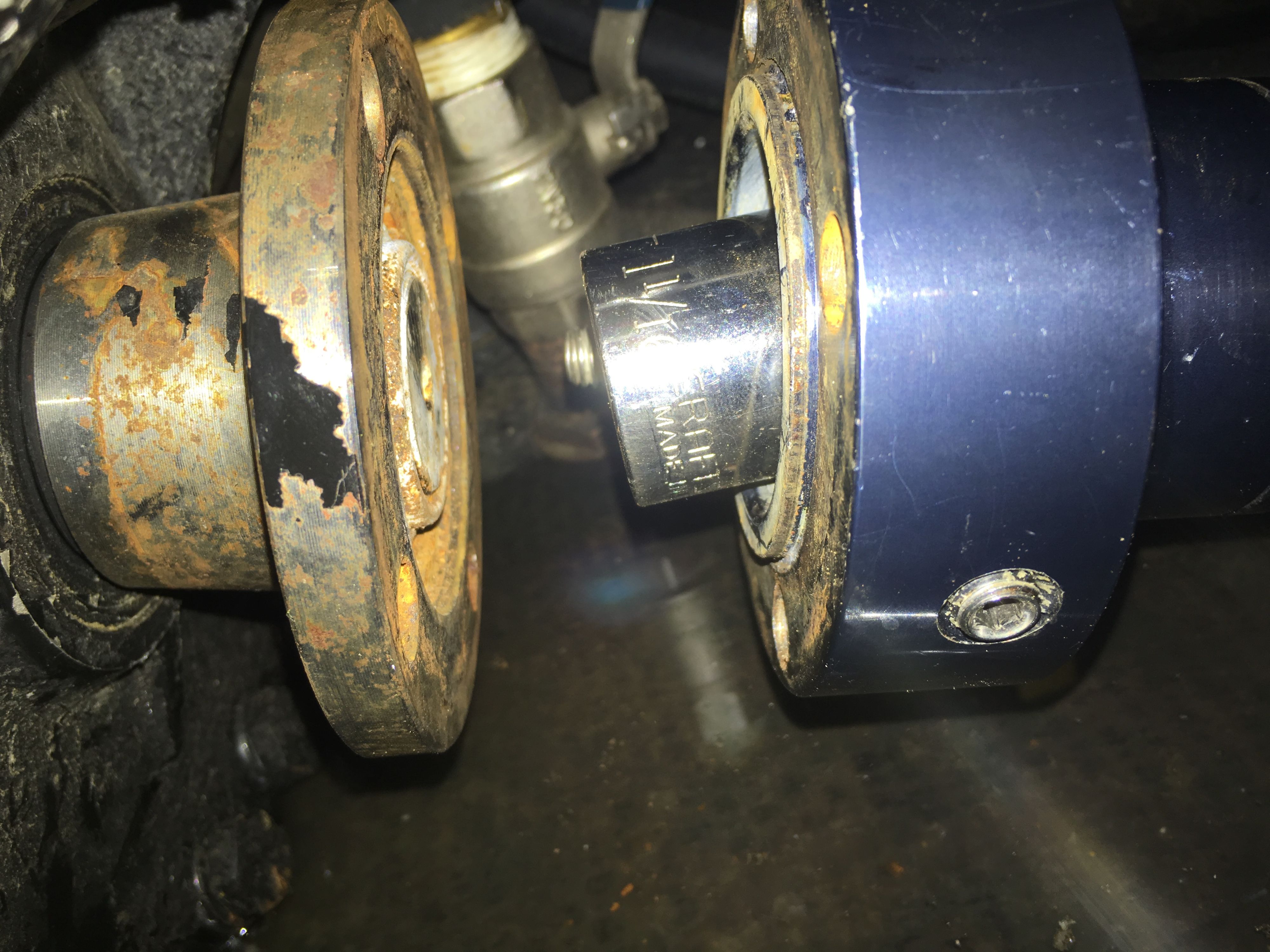
I've heard of some people welding a socket nut to a flat bar to make a skinnier wrench. The folks at Glide also gave me a good idea; to cut a socket in half to get it to fit in there with the socket wrench, which is what I did. I put the socket in a vise, then used a grinder with a cut-off wheel to cut the socket almost in half. Now I had a socket that fit over the nut, and provided enough width to use the socket wrench in between the flange and the coupler.

Can see it here. Now I could fit the wrench in there with the cut socket.
From there getting the nut off wasn't super easy either.... I had one of my stronger buddies hold the prop while I wrenched the nut off. Otherwise you'll need to improvise another way to keep is from spinning while you wrench on it.
But we got the nut off, and you can see here how it fit in the slimmed socket. 
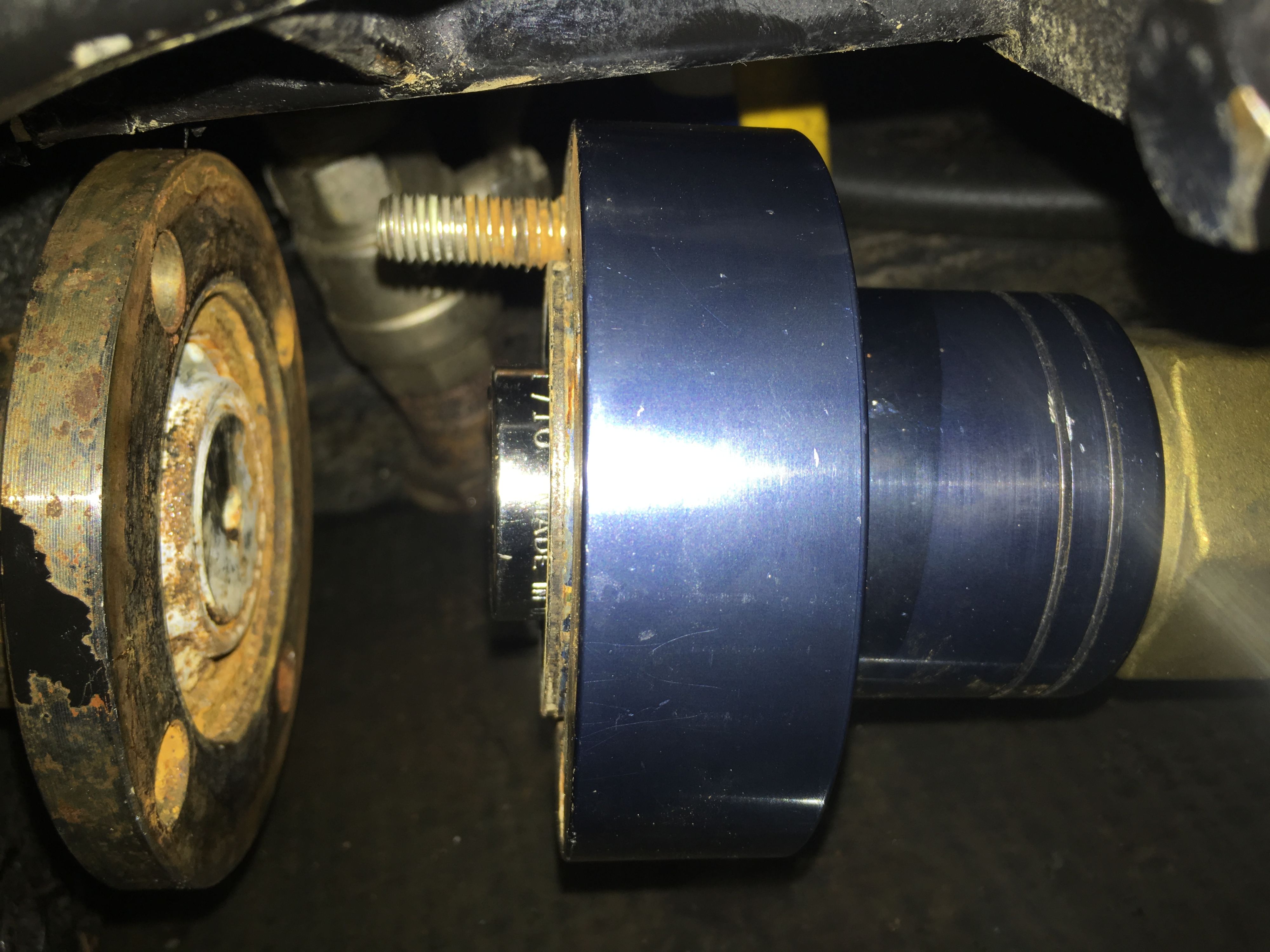
Next step was to get the drive shaft coupler off of the tapered drive shaft. There's a keyway in there and the coupler presses on the tapered end. It's a good idea to mark your driveshaft with a sharpie, to see where your coupler was positioned on it. Then when you put it back on, you'll have a reference to make sure it's on far enough etc.
To get the "pressed" coupler off the tapered driveshaft, I bought longer bolts (narrow thread) and placed a small socket between the drive shaft and the coupler. Then slowly tightened all four bolts until it pressed off. This took some torque, in fact once all the bolts were evenly tightened I switched to my battery powered torque gun and the coupler popped right off.


Once the coupler was off, I cleaned it up the best I could.
Next was the part where I actually get to replace the seal system with the new Glide system.
Here's the old system in place. Looks a little grungy after 11 years/ 500+ hours.

Next we pulled the driveline back out of the way and replaced the seal system.
Pulling the old brass shaft packing off was as simple as unscrewing the hose clamps that keep it snug around the brass shaft seal box attached to the hull. It came off without any problems.
Here's the old shaft seal with the brass compression nut and wax rope packing inside vs the new Glide GMSS seal kit, which is essentially maintenance free. You can see the hose barb off to the side of it, which will feed it water and keep it dripless. The inside looks like the Glide strut bearings, with a hump hose attaching to the hull shaft seal box just like the old one did.

Glide GMSS went on smoothly, tightened the two hose clamps over the shaft/hull box.


You also want to check you drive shaft to make sure it doesn't have permanent wear marks from the previous setup. Any light rings can be cleaned up with emery cloth to make sure the shaft is smooth and allow the new seal system to spin smoothly and wear in properly on the drive shaft. Forgot pictures of this, but we did clean up the driveshaft before reinstalling.
The GMSS kit comes with a small cardboard or alum spacer in between the top O ring. You want to keep this in place, so that when you push the drive shaft back up into it, the O ring seats nicely on the shaft and to prevent damage. The little cardboard spacer gets pushed out by the driveshaft and then you can just throw it away.
Once the driveshaft was back in and through the new GMSS, I could reinstall the tapered coupler onto the shaft. My coupler is aluminum and went right back on (referring to my previous marks, which also just meant tightening as far as it wanted to go). Just make sure your keyway is in correctly before doing this.
I also installed the water hose over the barb with the included hose clamp. Then routed the line out of the way and used the included stainless "T" fitting inserted into my raw water cooling line near the transmission. I just used my PVC pipe cutters to slice it and insert the T fitting. Quick and easy.
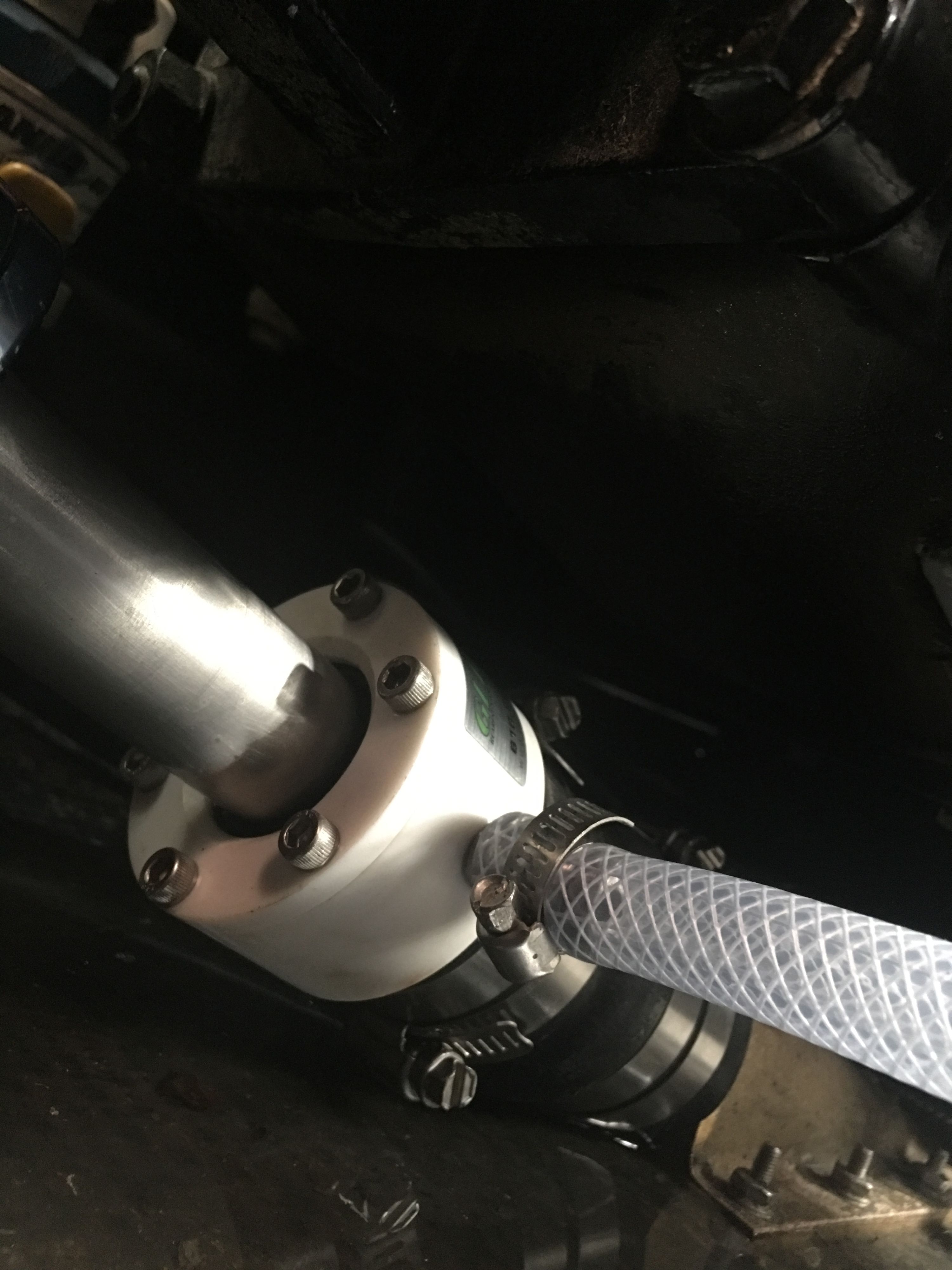


Once everything was put back together, I ran the water to my boat to make sure it didn't leak and ran the motor on the trailer. I did not put it in gear, but checked to make sure water was running through the T fitting to feed the GMSS, and that there were no leaks. All looked great.
We just spent 3 days with it on the water. Worked perfect. We also replaced the strut bearings (since strut had to be straightened). Between all these fixes my boat has run smoother - than it has since I've owned it. My guess is the strut bearings needed replacing anyway.
So if there's a silver lining in damaging my strut and prop -- it's forced me to replace all the seals on this 07 boat. Between the new shaft seals, the new strut bearings and the new rudder seals/rebuild kit -- the boat is "new again" below the water line.
Hope this write up and pictures help someone.
* forgot to mention I also did a quick check on engine to shaft alignment since I also removed the strut to get it fixed/straightened.
Loosened the bolts on the coupler slightly, used a feeler gauge between the coupler and v drive flange to compare the differences between top to bottom, and side to side. Looked for a difference - shooting for less than three thousands of an inch difference. I made zero adjustments in this case.
-
 4
4
-
 1
1


.thumb.jpeg.d318255b96edd9f88e9a0da37ff83595.jpeg)


.thumb.jpg.d6e1f49476f0797b86e8afb53e7c3295.jpg)


Recommended Comments
Create an account or sign in to comment
You need to be a member in order to leave a comment
Create an account
Sign up for a new account in our community. It's easy!
Register a new accountSign in
Already have an account? Sign in here.
Sign In Now